Schaffhausen 2000 - Accuracy of Artificial Athlete - Rules of Standardization - Lab Accreditation
S05Accuracy and Calibration of Artificial Athlete Berlin
Artificial Athletes - Accuracy & Round-Robin Results
Mark Harrison (CST London) and Bernd Härting (IST Leipzig)
The Artificial Athletes Berlin & Stuttgart have been specified in National and other Standards for about 25 years. Following their first appearances in the DINs they have been adopted by other European countries and by various world-wide sports governing bodies.
There have been no significant changes in the specifications based on the results of measurements made with the athletes. Specifically, for the Berlin Athlete, the force reduction specified for athletics surfaces has always been 35 to 50 %; for the Stuttgart Athlete, the vertical deformation has always been 0.6 to 1.8 mm.
There have been suggestions that the results from the Berlin Athlete in particular have changed systematically over the years. The grounds for these suggestions have been that products which were once thought to comply with the DIN specification are now found not to do so.
This is not the place to discuss all the possible explanations for an apparent change of this type. I want to describe the system which ISSS has recently put into place to ensure that no systematic change in the readings produced by various examples of the Berlin artificial athlete can take place in the future and, in passing, to show some of the reasons for my belief that there has been. no such change in the past.
The reasoning on which the ISSS Certification Programme for the Berlin Artificial Athlete is based is as follows.
Firstly, the AA Berlin consists of an assembly of mechanical components. Acceptable tolerances on these components have been defined - indeed are already defined in the DIN, but have, in some cases been tightened.
Secondly, acceptable tolerances in the processing of the electrical signals from the mechanical apparatus have been defined. Here, a significant refinement of the definitions in the DIN has been necessary.
If all the components of the apparatus are within tolerance, then of course the entire apparatus must be within tolerance as well. But there remains a small, possibly irrational doubt - the feeling that although everything should be all right, we don't know that it is.
The final stage of the process is therefore the testing of each piece of apparatus against known standard test pieces.
Let's start with the mechanical components of the apparatus (Figure 1). These are very few;
A mass
A spring
A circular, radiused foot
The properties of each of these are defined in the DIN to quite tight tolerances and, what is more, they are relatively easy to check. Nevertheless, it is interesting to look at the way variations in these components affect the outcome of the test, by calculating the peak force to be expected on a rigid substrate, with and without the test piece and assuming that the test piece acts as a linear spring.
Take the mass, defined in the DIN as 20 kg with a tolerance of 50 g. This graph (Figure 2) shows the effect of variations in the mass on the measured Force reduction for a range of ‘test pieces' having true FR from 15% to 90%. I chose to vary the mass by ± 5%, rather than the 0.25% maximum permitted by the DIN. The graph is interesting, because there is so little to see - the maximum error, which occurs at the hard end of the scale, is 0.1%.
This shows up one of the great strengths of the AA Berlin, which is that, because the result is the dimensionless ratio of two forces, many potential errors are greatly reduced because they affect both the baseline or reference force, measured on concrete, and the force measured on the test piece and the effect is in some cases identical (for instance errors in the gain of the amplifier system) and in others very similar (for instance errors in the falling mass and the spring rate).
There are other quantities which do not conveniently cancel in this way. One is the diameter of the test foot, a potential source of a constant error which would affect only the sample test. Another is the drop height, a variable error which would affect both reference and sample results. Consideration of the effects of all these factors and of their magnitudes leads to the conclusion that the outcome of the test is insensitive to errors in the mechanical parts of the apparatus.
The second aspect of the test is the processing of the electrical signal.
Many of the aspects of the signal acquisition and processing are relatively simple. The sampling frequency, the digital signal resolution and the use of an anti-aliasing filter are all set in accordance with well-established, standard practice. Determination of the peak value of the force is a simple matter after the signal has been properly processed to eliminate unwanted, confusing components which are mixed with the true test information, but this processing is itself less simple than is implied by either the basic description of the test or the foregoing considerations.
The basic description of the test says that you measure the maximum force on a hard reference floor and on the test sample. In its basic mechanics, the test, consisting of a 20 kg mass bouncing on a spring of rate 2 MNm-1, seems quite simple. This gives a signal having a fundamental frequency close to 50 Hz on a hard surface and becoming progressively lower on softer surfaces. For instance, with a surface giving a FR of 20%, this frequency is about 80 Hz, falling to 49 Hz at FR=50%.
As well as the fundamental signal, we record mechanical noise in the signal. This will be no surprise to anyone who has been looking the other way when a colleague has unexpectedly carried out a test. This record of a test (Figure 3) shows the noisy signal which is recorded and, superimposed, the clean signal we wanted in the first place and which we can extract by filtering out the noise. In this case, the noise is mainly the ringing of the coils of the spring and consists of two main components having frequencies of very roughly 2 kHz and 4 kHz. Because these frequencies are well above that of the interesting signal, we can easily filter out the unwanted noise, as here.
When we carry out a test on a real sample, things change. Going back to the diagram of the Artifical Athlete, we see that we have a mass and a spring - but we also have a second mass and a second spring (Figure 4), the test foot assembly and the sample itself. As well as the large mass bouncing on the combination of the two springs, the test foot oscillates between the large mass and the floor on the pair of springs. The frequency of this oscillation depends on the mass of the test foot assembly and the stiffness of the sample. The softer the sample and the heavier the test foot, the lower this frequency. With the test foot assembly having a mass of 3 kg, the frequency can be as low as 130 Hz on a soft sample.
This graph (Figure 5) shows the type of thing, in this case on a relatively hard sample, with the oscillation at a frequency of about 400 Hz.
This means that under some circumstances we want to throw away all components of the signal whose frequency is 130 Hz or greater and under other circumstances we want to keep all components whose frequency is 100 Hz or less. The selection of the type of filter and its characteristic frequency are therefore critical. This graph (Figure 6) shows the way in which 120 Hz Butterworth filters of different numbers of poles cut out the components of a signal. As you see, the 9-pole filter (which is the steepest achievable in practice) matches our requirements acceptably, with less than 2% attenuation at 100 Hz and over 60 % attenuation, climbing rapidly with frequency, at 130 Hz. However, the 5-pole filter causes unacceptable attenuation at 100 Hz, while the 2-pole filter has a serious effect on all signals down to 60 Hz and less (60 Hz corresponds to an expected FR of about 40%).
After dealing with the definition of the necessary filtration, other aspects of the signal acquisition and processing seem relatively simple. Determination of the peak value of the force is a simple matter after a carefully -recorded signal has been properly processed.
In the ISSS Certification Programme, these first aspects of the accuracy of a Berlin Athlete are dealt with as a paper exercise. A proforma has been prepared by Bernd Härting, who is operating the scheme from Leipzig. This form lists the defined parameters and provides a tick-list for supporting information. Bernd will be keeping records of all certified sets of apparatus. All IAAF labs are required to take part in the Certification Scheme. Others are welcome to participate.
The final stage of the Certification Program is the testing of the Athlete against known standard test pieces.
The use of Reference Standards has been talked about as a kind of unachievable dream for some years. The obvious things to use would be pieces of athletics surfacing, but there are many objections to these - to start with, linearity, uniformity, reproducibility and ageing. That we now have a reproducible, reliable device is due to SKZ, who have devised an entirely metallic Reference Norm for use with the Berlin and Stuttgart athletes. The device consists of an assembly of conical steel spring washers in a housing (Figure 7). Because it is metallic, there is no risk of changes due to the type of ageing which is unavoidable with polymers. Steel springs are also practically free from the unpredictable damping effects which could affect matters if a polymeric reference were used. The use of conical springs in series avoids the non-linearities which would be expected if an assembly of helical springs in parallel were used. The spring rate can be adjusted to fine tolerances and, by careful selection of the washers, a high standard of linearity can be achieved.
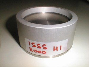
Several sets of Reference Norms have now been made (Figure 8). Each set consists of three Norms, of different hardnesses representing different points on the Force reduction Scale. As part of the Certification Process, a lab is supplied with a set of Reference Norms on which to carry out ordinary Force reduction tests.
It is important to be clear what is being achieved here. A standardised object whose FR value can be determined by static measurement and calculation - independent of the apparatus being checked - is being used as a standard through which a number of pieces of apparatus can be compared. The reference system is thus externally defined and is verified against external standards.
An alternative system which has been proposed is the use of a ‘Standard Athlete', with whose previously determined values all other athletes must agree. A system of this type would be self-referential. Even if the Standard Athlete were calibrated against a set of Reference Norms, its values would be subject to the same uncertainties and tolerances as any other working athlete, so would be of no greater validity than values determined with any other athlete.
The first round of the ISSS Certification Programme for Artificial Athletes is now complete. All IAAF labs have submitted the required data and have carried out the required tests on Reference Norms.
I would expect that all the values on any given reference should be within 1% of the mean of all results on that Reference. The majority of the results from the first round robin satisfy that criterion, though there has been a small number of outlying results. These are being investigated by the labs concerned.
This first Round-Robin represents only the first stage of the Certification programme. After refinements and the identification of the sources of error, a second Round will be held, in which the criterion mentioned should be satisfied.
It is important to be aware that the Berlin Athlete Force Reduction test, like any method of measurement, is subject to uncertainties. The purpose of this Certification Programme is to identify those uncertainties and to reduce them as far as is possible. The round robin data demonstrate that the intended reductions are feasible and will be achieved.
Figure 1 - Essential mechanical components of the Berlin Athlete
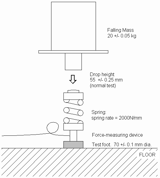
Figure 2 - Influence of a 5% mass error on the results produced by the Berlin Athlete
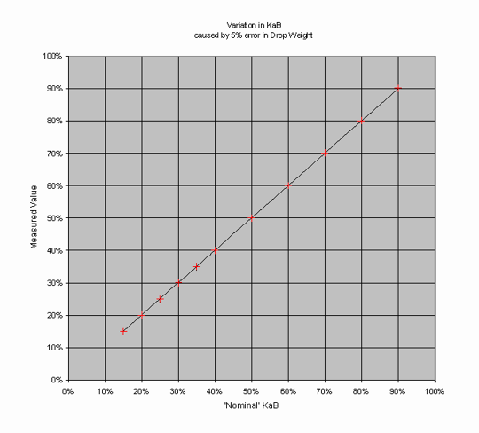
Figure 3 - Test on concrete, showing both crude and filtered data
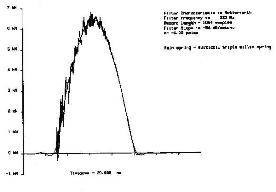
Figure 4 - Representation of the Berlin Athlete as a 2-mass/2-spring mechanical system
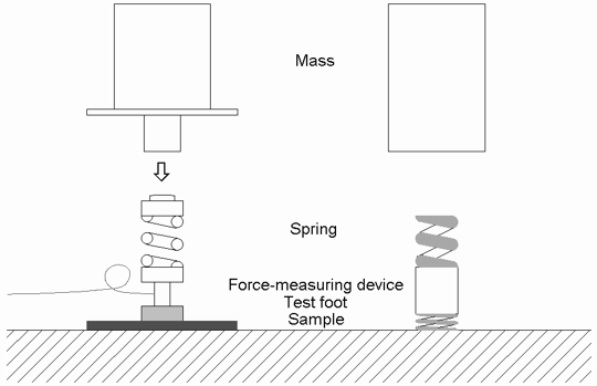
Figure 5 - Superimposed oscillations recorded on a sample
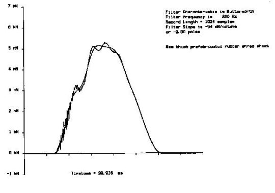
Figure 6 - Effects of different Butterworth filters on overall frequency response of a system
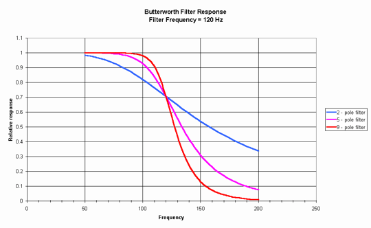
Figure 7 - Cross-section of Reference Norm
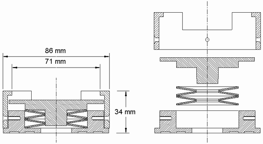
Figure 8 - Photograph of the Reference Normal
Lausanne: 28 & 29 November 2024
The ISSS has successfully concluded the AGM and the Technical Conference in Lausanne. Scientific and Individual Members present accepted financials, audit report and activity schedule as presented.
Details Here